Product Design (KIS)
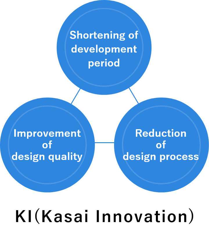
KIS
(Kasai Innovation System)
This is our own next generation technology.
KIS is our interior parts development system established to meet the requests of automobile manufacturers to shorten the development period.
About KIS
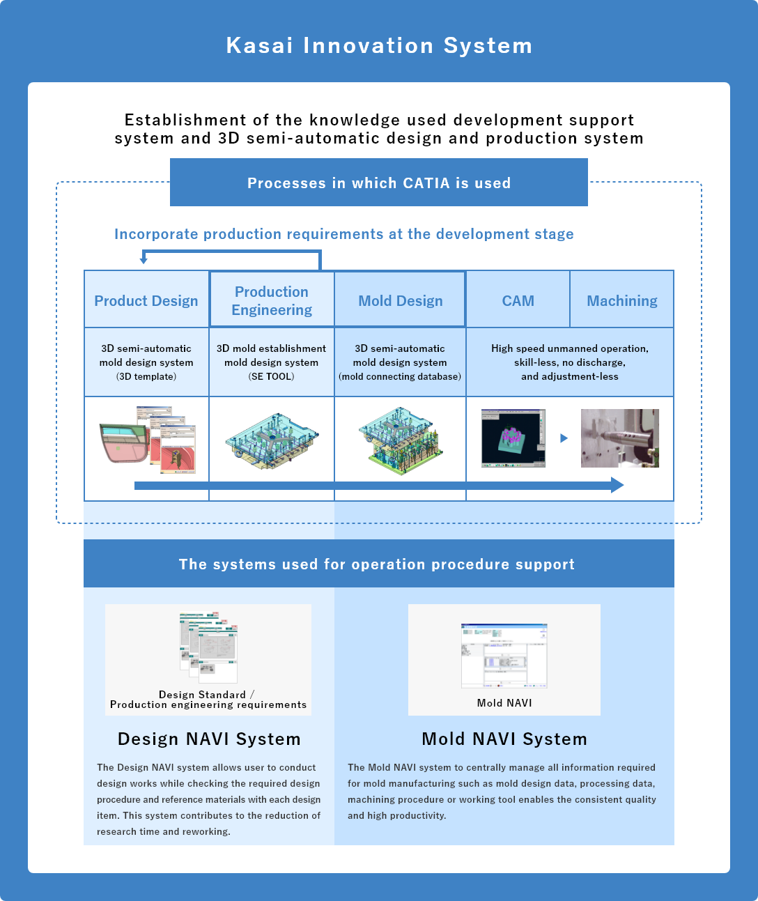
At the development phase, we standardized our know-how concerning the manufacturing of Kasai's principle products such as door trim, and such standardization of know-how enabled semi-automated development (3D CAD templates).
As a result, we made it possible to prepare for development and production comprehensively from product design to mold manufacturing, and realized to shorten the development period.
At the mold production phase, we apply the 3D CAD DATA for cutting technology, which contributes to shortening the cutting period of mold with fewer craftsmen than before. We strive to manufacture high-quality and consistent molds for customers with 100% dimension approval rate in a much shorter period of time on the first delivery.
KIS system that supports from product design to mold making
Product Design
For product designing, we employ 3D template to study customer's specification conditions and our manufacturing requirements.
This 3D template contributes to the shortening of design period and improvement of design quality by semi-automatic product designing.
3D semi-automatic design system (3D template)
-
01 Procedure of 3D template
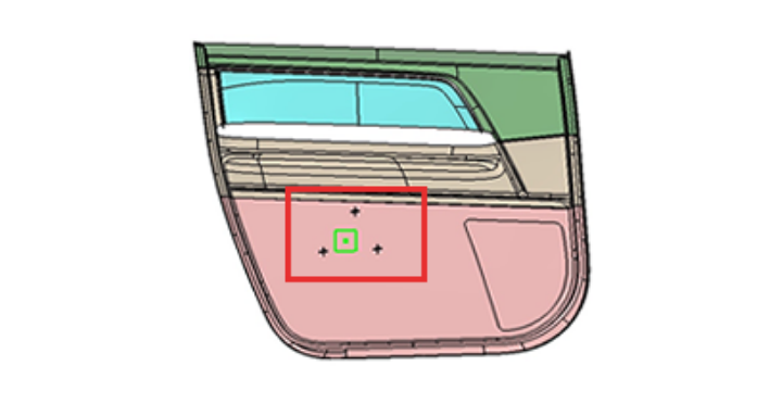
The following is the procedure to put the template of a fixed body shape within the red frame of a door trim.
-
02 Creation of fixed position
(input element)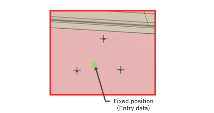
When creating a fixed body shape, create the information (input element) necessary to use the template without creating the shape from scratch. As this figure shows, create a point at a fixed position.
-
03 Automatic creation of a shape
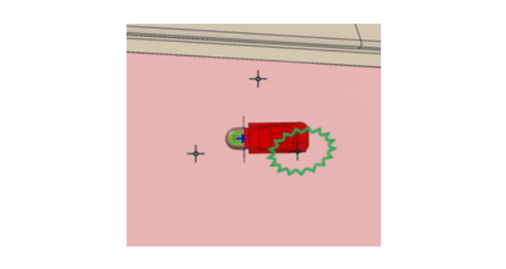
A shape is created automatically by using a template for a fixed position. As shown by this figure, the initially created position of a template interferes with other structure.
-
04 Study of shape feasibility
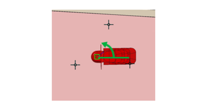
Any shape created by a template can be adjusted in accordance with various requirements such as design, mold and production engineering requirements.
As this figure shows, adjust an angle to the appropriate position that has no interference with ohter structure. -
05 End of study
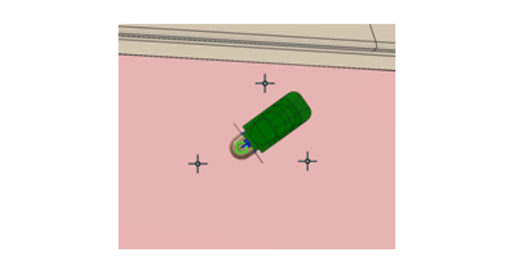
The shape position is changed by adjusting an angle. This system allows the semi-automated shape creation. This contributes to the reduction of design time and improvement of design quality.
Production Engineering
Production engineering staff, based on the data provided from the product design team, examine the feasibility of the mold using a simple mold structure module (SE TOOL).
This study contributes to the solving of mold structure related problems one by one at the development stage.
3D Mold Feasibility Study System (SE TOOL)
-
01 Selection of a structure
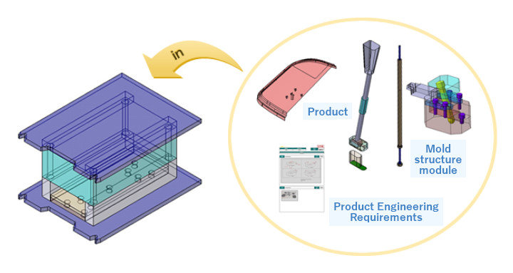
Select a mold structure module based on product shape studied by design and production engineering requirements.
-
02 Check of mold structure feasibility
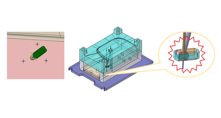
Any problems related to mold structure feasibility not identifiable by product alone can be checked by mold structure module.
-
03 Feedback on mold feasibility problems
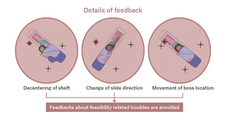
In case of feasibility problems for mold structure, provide the feedback to product design staff about mold structure change or change request of product shape.
-
04 Check of corrected product data
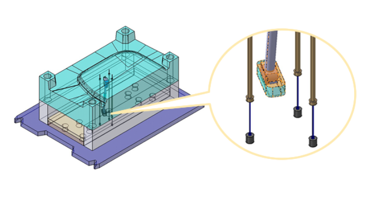
Check whether or not the content of feedback are corrected. Digital lot related issues can be solved by repeating this study and feedback.
Mold Design
Based on data from production engineering staff, mold is designed in detail applying mold master models and mold design module (3D semi-automuted mold design system). Mold master model and mold design module allow the significant reduction of mold design period and mold production with consistent quality.
3D Semi-automatic mold design system (mold linked database)
-
01 Input of mold specification data
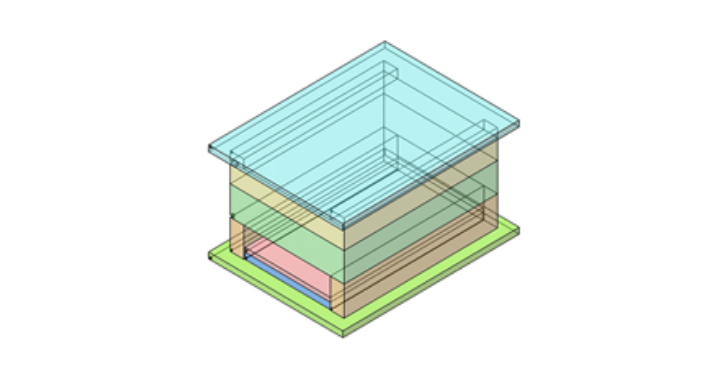
A master model of the mold is created semi-automatically by inputting the parameter of the mold specification data examined by the production engineering staff.
-
02 Automatic placement of mold parts
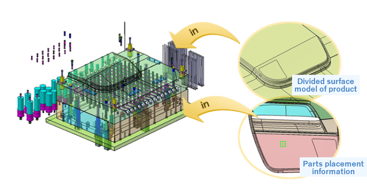
The mold concept can be designed semi-automatically by inputting the divided product surface model of the mold and the component placement data.
-
03 Detailed design of mold
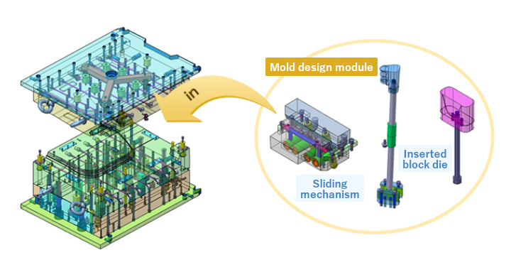
Furthermore, the necessary mold parts are placed, and the detailed design of the mold is performed by adjusting the dimensions, position, and shape parametrically. This greatly shortens the mold design period and enables the production of molds in consistent quality.